

NFPA 72, National Fire Alarm and Signaling Code, 2025 Edition was released in the fall of 2024. The origins of what is now NFPA 72 date back to 1899, and every update allow the code to evolve based on the new technologies and current design considerations.
NFPA 72, 2025 Edition requires that the owner be notified of an impairment, of the whole system or part of the system, within 8 hours. Deficiencies are still required to be reported to the owner in writing within 24 hours. (72-10.21)
Chapter 11, Cybersecurity, which was previously annex material, was added to NFPA 72. Chapter 11 requires a security level based on the level of equipment access remotely or over the Internet. Chapter 11 specifies testing and maintenance with regular security updates per ANSI security standards.
Previous editions of NFPA 72 did not specifically address a maximum mounting height for spot-type smoke detectors, only required that is air patterns or stratification were a concern that a performance based should be done. The 2025 Edition states the spot-type smoke detectors may use 30 foot (accepted) spacing up for ceiling up to 40 feet. Ceiling above 40 feet require a performance-based design. This change was driven by a study by the NFPA Fire Protection Research Foundation. (link to article – 241114033151-RFSDSpacingPhII_NFPA72.pdf ) (72-17.7.4.2.3.1)
The 2025 Edition changed the inspection and testing intervals for control valve supervisory and waterflow alarm devices, setting semiannually as the interval for both inspection and testing for both devices. Other supervisory devices still require semiannual inspection, and annual testing. (Table 14.3.1 and 14.4.3.2)
The 2025 Edition introduced a new audible notification mode: restricted audible mode notification (RAMO). RAMO is intended to be used in areas where sudden loud noises could adversely impact occupants, and is intended to provide notification without causing undue stress. RAMO notification is required to be indicated on the drawings, and requires that trained, awake and mobile staff are present. RAMO requires 520 Hz audible notification and permits private mode sound levels (10 dB above average ambient). RAMO also requires annual testing and documentation. (72-18.4.8)
The 2025 Edition provides some additional clarity for voltage drop calculations for notifications circuit. The code specifies the requirements for DC (horn and strobe) and AC (speaker) circuits, and includes considerations for start voltage, appliance current, control (notification) module loss, and circuit length. (72-18.3.7)
The calculations begin with control unit start terminal voltage (CUSTV), which is the minimum voltage for the NAC circuit based on the requirement for the control unit to operate at 85% of its nameplate voltage. For a 24 volt fire alarm system, the CUSTV is 20.4 volts.
The notification appliance current in the calculations uses the device current at the lowest voltage, which is 16 volts for a 24 volt notification appliance. This figure, commonly called “UL Max” is commonly used on notification appliance data sheets as the current requirement for the appliance.
For notification circuits operating from an addressable notification module, the voltage loss through the module is included in the calculation. This loss through the module, called a module voltage adjustment (MVA), is deducted from the input voltage to the module.

AC notification circuits, which are speaker circuits are calculated differently. AC notification circuits are designed for a maximum of 1.0 dB of electrical loss, with 0.5 dB maximum loss recommended. If notification modules are used to operate the circuit, a module insertion loss (MIL) in included in the calculation.
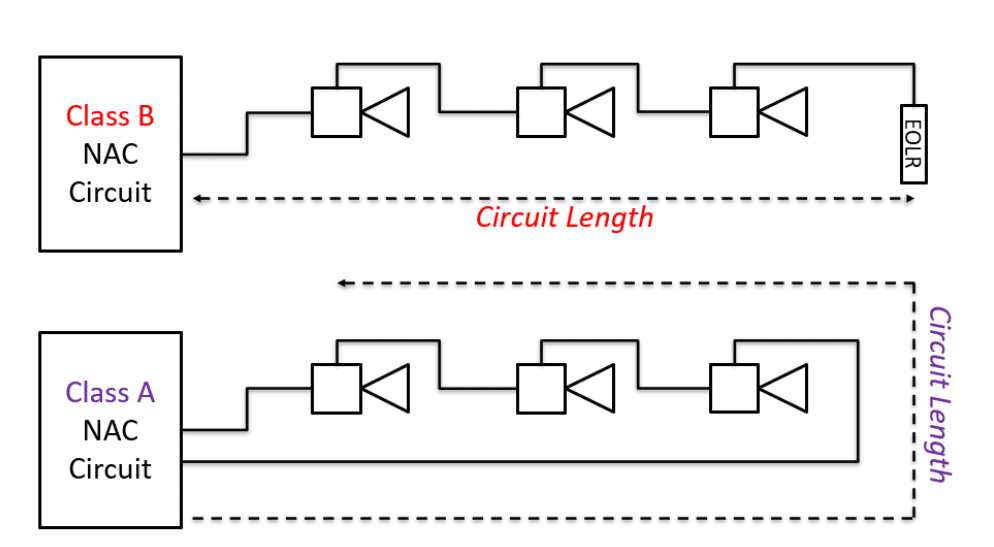
The 2025 Edition also provided clarification for the methods used to calculate circuit length. Class B circuits are calculated from the start to the last appliance on the circuit, while Class A circuits are calculated from the start to the last appliance on the longest side of the circuit. The circuit length calculation is also required to all wiring to get to the notification appliance, including distance from panel to ceiling, vertical wiring between floors, drops to ceiling mount appliances, and the service loop in a junction box.
The Code further defines the calculation method used to perform the calculation, requiring clarification if the length is based on circuit length (distance based on cable pair to the last device on the circuit) or circuit distance (electrical distance of the circuit. The wire resistance is required to be pulled from NFPA 70 – Conductor Properties (Chapter 9, Table 8) or manufacturer’s data sheet. The calculation may be calculated as end-of-line loaded (ELL), which is based on all appliances at the end of the circuit, or point-to-point, which calculates voltage drop from device to device using actual cable distances.

The 2025 edition changed the installation requirements for emergency control function interface (ECFI) devices. The ECFI may be located with 3 feet of component controlling the emergency control function without and special requirements. The 2025 Edition also permits the ECFI to be installed within 20 feet of component controlling the emergency function if the cabling is installed in metal raceway or armored cable. These requirements apply to Class A, B, N, or X, but do not apply to Class D (failsafe) circuits. (72-21.2.4)
The 2025 Edition added requirements for auxiliary service provides (ASPs). ASP’s process signals for performance-based communicators, such as IP and cellular communicators. ASPs are required to have their communications path to the supervising station supervised every 90 seconds, and their facilities are required to meet UL 827 (Central Station Alarm Systems). The building owner, AHJ, and supervising station are required to be given written notice of the use or change of an ASP within 30 days. (72-26.2.11)

Want to learn more about NFPA 72 (and other codes related to fire alarm systems), check out the 2025 Edition of the NTC Brown Book (Fire Alarm Systems Handbook).
