

The National Electrical Code (NEC), NFPA 70, is the universally adopted Code for all electrical work in buildings in the United States. The stated purpose of NFPA 70 is the safeguarding of persons and property arising from the use of electricity.” While most fire alarm technicians consider the requirements of NFPA 70 to be the domain of electricians, the requirements of NFPA 70 do specifically apply to fire alarm systems as well.
General Requirements
Chapter 1 of the National Electrical Code covers common definitions used in the Code and general requirements for electrical installations. The definitions in Article 100 are important and form the basis of the code requirements. Therefore, it is important to read and understand the definitions in this chapter to understand the requirements that pertain to them.
Some important definitions include:
- Branch circuit – conductors between the final overcurrent device protecting the circuit and outlet(s) or equipment
- Cabinet – enclosure with a swinging door
- Overcurrent protective device – a device that interrupts the circuit when current exceeds a specified amount (i.e., circuit breaker or fuse)
- Raceway – enclosed channel for holding wires (i.e., conduit)
Article 110 covers general requirements for electrical installations. An important requirement from Article 110 is working space. Equipment operating at up to 150 volts, including a 24V fire alarm system, requires a minimum of 3 feet of working space in front of the cabinet. The width of the working space is 30 inches, or adequate to allow the cabinet door to open to 90 degrees, whichever is greater. The height of the working space is required to be at least 6 1/2 feet or to the top of the cabinet, whichever is greater.
Chapter 2 of the National Electrical Code covers wiring and protection. Most of Chapter 2 pertains to building electrical wiring requirements and would apply to the primary power wiring going to a fire alarm system, since this wiring is typically the electrical contractor’s responsibility, not the fire alarm contractor’s.
Chapter 2 also contains Article 250, Grounding and Bonding. The primary purpose of grounding and bonding is to prevent accidental electric shock by providing a safe path to ground for electrical circuits. Grounding provides the path to the ground, and bonding ensures that all electrical circuits use the same path to the ground. While the Code does not require fire alarm systems to be grounded, most equipment is grounded for surge protection and to supervise ground fault conditions.
Chapter 3 of the Code governs wiring methods for all circuits, including those with voltages of 1000 volts or less. This chapter generally applies to all electrical work, including low-voltage systems. Chapter 3 is a key chapter of the Code in terms of wiring requirements. The proper installation of electrical wiring is crucial for providing safe and effective electrical systems within the building. Here are some basic requirements that generally apply (including fire alarm systems wiring):
- Wiring installed under roof decking is required to be at least 1 ½ inches below the roof decking
- A junction box is required for each splice or termination point
- Penetrations in fire barriers are required to be properly sealed
- Wiring inside ducts is not permitted unless wiring applies to the direct functioning of the duct
- Wiring or raceway installed in environmental air return spaces is required to be plenum-rated
- The installation of wiring cannot impede the removal of ceiling tiles
- The number of conductors permitted in an outlet box
- Approved bushings are required for conductors passing through a junction box knockout
Article 760 – Fire Alarm System
Article 760 of the National Electrical Code (NFPA 70) governs fire alarm systems. The requirements of Article 760 are broken into four parts: General, Non-Power-Limited Fire Alarm (NPLFA) Circuits, Power-Limited Fire Alarm (PLFA) Circuits, and Listing Requirements.
The general requirements in Article 760 include definitions specific to Article 760, other Articles that apply to the fire alarm, and general fire alarm installation requirements. Definitions include abandoned fire alarm cable (not terminated at equipment and not tagged for future use), non-power-limited fire alarm circuit (circuit powered without a current limiting power source, such as a 120V fire alarm system), and power-limited fire alarm circuit (circuit powered by a current limiting power source, such as most modern 24V fire alarm systems).
Article 760 refers to other Articles within the Code for specific requirements that apply to fire alarm system wiring. Many referenced Articles are part of Article 300 (General Requirements for Wiring Methods and Materials). Still, the Code specifies that only the specifically referenced Articles apply to fire alarm systems, not all the requirements from Article 300.

The general requirements in Article 760 state that all fire alarm circuits are installed neatly and workmanlike. Cables are permitted to be exposed on surfaces or ceilings, and sidewalls, but are required to be supported by the building structures so that they won’t be damaged by normal building use. Additionally, the method of support shall not damage the cables.
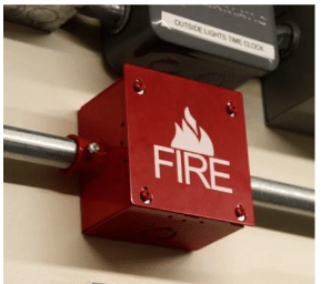
Article 760 requires fire alarm circuits to be identified at terminals and junctions. However, the Code does not specifically identify the identification method, leaving this to the AHJ. Common identification methods include junction boxes, labeling box covers with the words FIRE ALARM, or using a fire icon. Additionally, the Code does not specify the method of splicing cables, leaving this decision to the discretion of the AHJ.
Article 760 general requirements also refer to other articles for hazardous locations (environments with combustible or explosive gases, vapors, and dust), remote control circuits (elevator control, fan shutdown), and fiber optic cable when utilized with fire alarm circuits. These requirements apply when fire alarm circuits are installed in these locations or applications.
Non-Power-Limited Fire Alarm (NPLFA)
Article 760 separates fire alarm circuits into Non-Power-Limited Fire Alarm (NPLFA) Circuits and Power-Limited Fire Alarm (PLFA) Circuits. Each circuit classification has specific installation, cable, and application requirements.
Non-Power-Limited Fire Alarm (NPLFA) circuits do not have any inherent current limitations. Since NPLFA circuits do not have the current limiting features of a power-limited circuit, they provide a greater risk of electric shock and have more stringent installation requirements. Nonpower-limited fire alarm circuits are permitted to operate at up to 600 volts.
The best example of an NPLFA is a legacy 120V fire alarm system. Since NPLFA fire alarm systems present a risk of electric shock (like any other building’s power wiring), the cable must be installed in accordance with the requirements of Chapters 1-4 of NFPA 70. The cabling is typically conducted and treated like any building power wiring circuit.
The rating of the overcurrent protection device (circuit breaker or fuse) is based on the gauge of cable used for the circuit conductors. For example, 18 AWG conductors require a 7-ampere overcurrent device, while 16 AWG conductors require a 10-ampere overcurrent device. Therefore, larger gauge cables permit larger ampere overcurrent devices, depending on the gauge and type of cable used.
Power-Limited Fire Alarm (PLFA)
Power-Limited Fire Alarm (PLFA) circuits receive their power from an inherently power-limited power source that limits the current to the circuit. These power limitations on the circuit significantly reduce the risk of electric shock and provide greater flexibility in cable installation. Power-limited fire alarm systems receive power from a PLFA or Class 3 transformer or power supply, either of which provides the power limitations required for the fire alarm system.
Most modern 24V fire alarm systems are power-limited fire alarm systems. Since the wiring of PLFA fire alarm system circuits presents a much lower risk of electric shock, the cable installation requirements are much less stringent. Therefore, the installation requirements of PLFA circuits are more intended for the protection of the cable than the protection of the building occupants.
Since power-limited fire alarm systems utilize transformers or power supplies to step down the operating voltage of the system and provide the required power limitations to the circuit, NFPA 70 identifies wiring for these systems as supply-side and load-side wiring. Supply-side wiring refers to the non-power-limited side of the wiring (primary power) that enters the fire alarm panel. Therefore, supply-side wiring is required to be installed according to Chapters 1-4, which would include the same protection requirements as a non-power-limited fire alarm circuit (run in conduit, treated like other building power wiring).
The load-size wiring is powered by the fire alarm control panel using a power-limited power source, so the wiring requirements for load-side wiring are much less stringent than the supply-side wiring requirements.
Learn more about fire alarm wiring requirements in the NTC Brown Book, Fire Alarm Systems Handbook.
